
Getting started
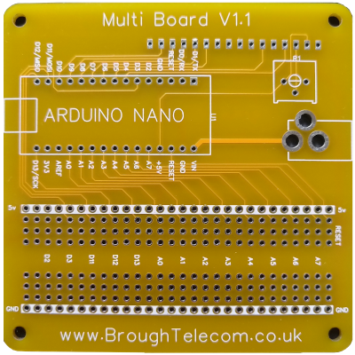
Brough Telecom Multi Board
Let's make your Arduino project permanent.
Planning
It's vitally important that you plan your project before assembly. The lower half of the board is laid out in a manner that echoes that of many wireless breadboards. The top row is the 5volt the bottom row is the ground. All of the available ports are brought out on alternative columns as marked. If you require more space the pins of unused ports can be omitted when installing your nano.Assembly
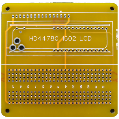
While the components that comprise your design can be fitted to either side of the board it is vitally important that the nano and the LCD components Are fitted as shown on the screen printing. To be as compact as possible the LCD must be fitted last to allow access for soldering of the nano, variable resistor and optional barrel connector. Attaching the nano with the pins upside down and insuring that contact the LCD on the other side of the board is avoided.Powering
While the best way to power your project is via USB, provision has been made for an optional barrel connector. Please remember that the barrel connector is connected to the raw import of the nano who's regulator may not be powerful enough for your project.Test Sketch
Once the basic components are Correctly installed load and run the test sketch. If everything is working correctly things should look like the video below. If the display doesn't look like the video below you may need to adjust the variable resistor which will vary the contrast of the LCD.
////////////////////////
//     Multi V1.1     //
//                    //
//  Multi Board V1.1  //
//                    //
//   Test and demo    //
////////////////////////

#include <LiquidCrystal.h>

///////////////////////////////////////////////
// select the pins used on the LCD panel     //
///////////////////////////////////////////////
//  LiquidCrystal lcd(RS, E, D4, D5, D6, D7) //
LiquidCrystal lcd(4, 5, 6,  7,  8,  9);
///////////////////////////////////////////////

const int Backlight = 10;  // A

const int colums = 16; /// have to be 16 or 20
const int rows = 2;  /// have to be 2 or 4

void setup() {

  pinMode(Backlight, OUTPUT);
  analogWrite(Backlight, 255);

  lcd.begin(colums, rows);
  lcd.clear();              // Clear the display.
  delay(1000);
  lcd.setCursor(0, 1);
  lcd.print("Multi Board V1.1");
  lcd.setCursor(1, 0);
  lcd.print("Brough Telecom");
  delay(5000);
}

// the loop function runs over and over again forever
void loop() {
  backLightDemo();
}

void backLightDemo() {
  lcd.clear();
  lcd.setCursor(0, 0);
  lcd.print("D10 controls");
  lcd.setCursor(0, 1);
  lcd.print("LCD Backlight");
  delay(5000);

  lcd.clear();
  lcd.setCursor(0, 0);
  lcd.print("using :- ");
 lcd.setCursor(0, 1);
  lcd.print("analogWrite(D,i)");
   delay(5000);

  lcd.clear();
  lcd.print("analogWrite");
  lcd.setCursor(8, 1);
  lcd.print("(10,   )");


  for (int t = 5; t >= 0; t--) {
      for (int i = 255; i >= 0; i--) {
    analogWrite(10, i);
    lcd.setCursor(12, 1);
    lcd.print("   ");
    lcd.setCursor(12, 1);
    lcd.print(i);
    delay(20);
  }
  for (int i = 0; i <= 255; i++) {
    analogWrite(10, i);
    lcd.setCursor(12, 1);
    lcd.print(i);
    delay(20);
  }
  }
  delay(1000);
}
DOWNLOAD Multi_V1.1.ino